PRODUCT
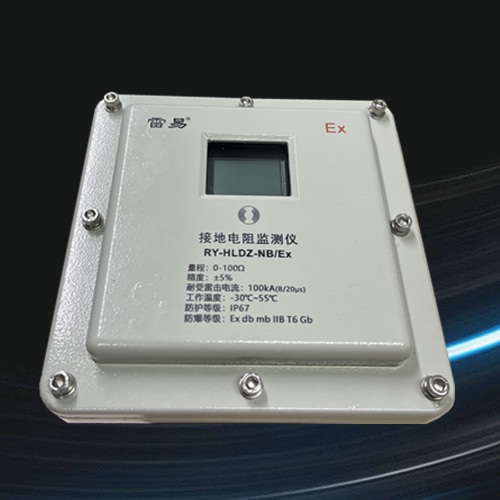
Explosion proof Grounding Resistance Monitoring System
Explosion proof grounding resistance monitoring instrument
1.Product Introduction
The RY-HLDZ LoRa/Ex and RY-HLDZ NB/Ex explosion-proof grounding resistance monitoring devices are carefully designed and manufactured for online monitoring of the connection status of grounding down conductors, loop grounding resistance, and metal loop connection resistance. This monitoring device is capable of online testing and non-contact measurement. The grounding wire passes through the core without the need for self inspection and real-time detection. It is suitable for grounding transmission line towers; Grounding of underground mine equipment; Meteorological lightning protection grounding; Petrochemical grounding; Communication grounding; Grounding of substation and distribution station; Grounding of railway facilities; Grounding of building warehouse; Electrical equipment grounding and other places can also be used for anti-theft monitoring of grounding wires and metal cables.
RY-HLDZ LoRa/Ex is a LoRa wireless communication model that can be used in conjunction with a LoRa gateway to achieve remote online real-time monitoring of grounding resistance values. RY-HLDZ NB/Ex is a NB wireless communication model that can measure the grounding resistance value at regular intervals and upload the collected data to the server through the NB network. Users can log in to the platform using the manufacturer's backend management system account to view the real-time status of the monitoring instrument and the collected data.
2.Product appearance and dimensional drawing
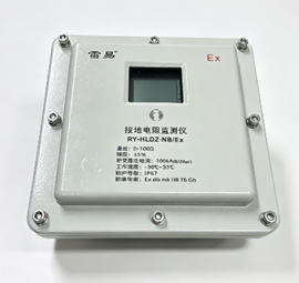
Figure 2-1 Appearance of Explosion proof Grounding Resistance Monitoring Instrument
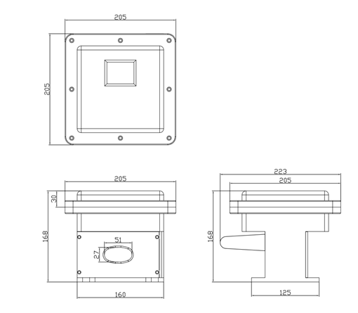
Figure 2-2 Dimension diagram of explosion-proof grounding resistance monitoring instrument
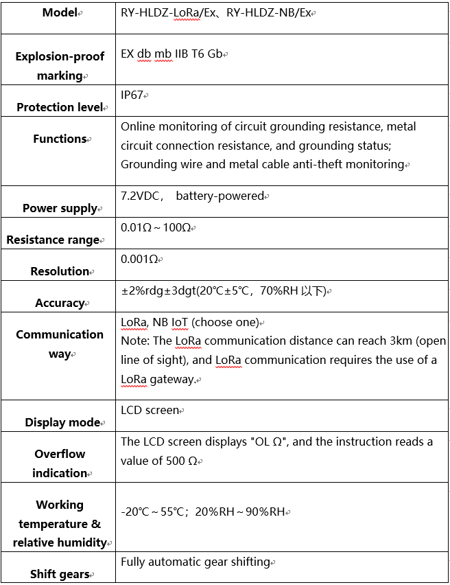
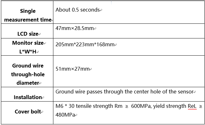
3.Technical specifications
4.Instructions for the LCD screen display of the monitoring device
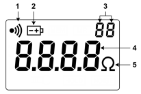
(1)Alarm symbol
(2)Low battery voltage symbol
(3)Storage data group number digits
(4)Measurement value display
(5)Resistance unit symbol
5.Instructions for using the monitoring device
1. Independent installation and use
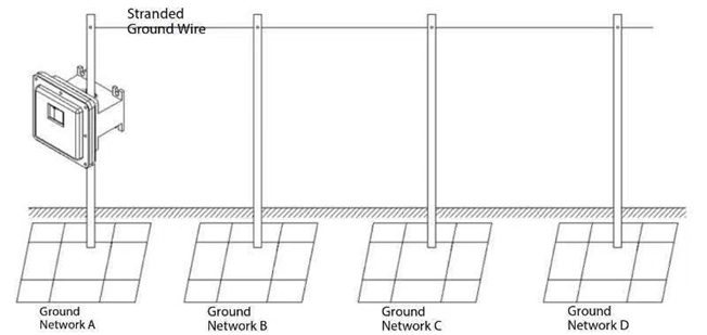
2.Topology diagram of tank area grounding system
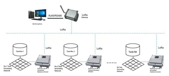
Each tank grounding network in the tank area is equipped with a LoRa communication version explosion-proof grounding resistance monitoring instrument to achieve real-time online monitoring of grounding resistance. The data collected by the monitoring instrument is transmitted to the LoRa gateway through wireless LoRa signals, and then sent to the monitoring backend through wired network ports or RS485 communication interfaces
For tank farms with large distribution areas and long communication distances, it is possible to exceed the communication distance of the LoRa network. In this case, if conditions permit, a LoRa gateway can be deployed in different areas, or LoRa relay nodes can be added in the middle of distant nodes.
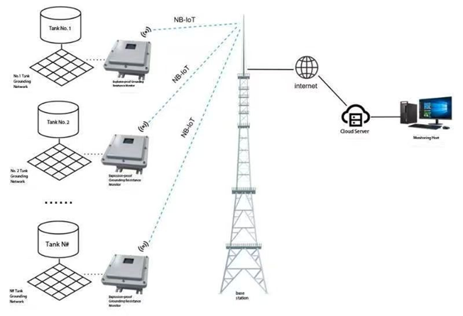
Each storage tank in the tank farm is equipped with an NB communication version explosion-proof grounding resistance monitoring instrument to achieve real-time online monitoring of grounding resistance. The monitoring instrument will collect grounding resistance data at regular intervals and upload it to the cloud server through the NB network. The NB communication scheme has a wider coverage range and supports massive device connections compared to the LoRa communication scheme.
6.Detection principle and application
1. Detection Principle
The basic principle of measuring grounding resistance with this explosion-proof grounding resistance monitoring device is to measure the circuit resistance. The sensor first provides an excitation pulse signal to the tested grounding circuit, inducing a pulse potential E on the tested circuit. Under the action of the potential E, a current I is generated in the tested circuit. The sensor measures E and I, and obtains the resistance of the tested circuit through the formula: R=E/I.
2. Definition of circuit resistance
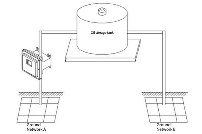
As shown in Figure 6-1: The circuit resistance includes the grounding resistance value from point A to ground, the resistance value of the metal conductor of the grounding down conductor, the resistance value of the metal overhead line, the connection resistance value (contact resistance) between the grounding down conductor and the metal overhead line, and the comprehensive value of the grounding resistance value from point B to ground. For the grounding system that forms the above circuit, a detector can be directly installed for monitoring. If there is no grounding system that forms a circuit, an auxiliary grounding electrode needs to be added to form a circuit, and then a detector can be installed. See the single point grounding system described later.
3. Connection resistance detection of metal circuits
Figure 6-2
If grounding network A and grounding network B are connected together on the ground, the detector will test the resistance value of the metal circuit, which is usually very small, a few tenths of an ohm. This is the connection resistance value of the metal circuit, which is also the equipotential resistance value, not the grounding resistance value. So this detector can also conveniently detect the connection resistance value of metal circuits, achieving anti-theft monitoring of grounding wires and metal cables. When the cable is cut and the metal circuit resistance is infinite, the detector will sound an alarm.

